
Elite PI screen is blank, black, or keeps rebooting
A dark Elite PI is almost always diagnosed from the back of the unit, not the front. The main (green) processor board behind the LCD has a small two-digit red display and, right below it, a blue LED labeled ACT. Those two indicators tell you whether the board is alive and whether its two processors are still talking to each other.
My Elite PI screen is black but the two-digit display on the back still shows the floor. What does that mean?
The position-indicator side of the board is working, but the graphics processor is not, so the unit has to go back to CE for repair. The two-digit display showing the correct floor (or dashes while the car is on inspection) only proves that the board is powered and receiving car position; it does not prove the display processor is running.
- Look at the back of the unit. You should see the green main board with the fan and heat sink, the two-digit red display, and the blue ACT LED directly below it.
- Watch the ACT LED. In a healthy unit it blinks continuously, like a heartbeat.
- If the screen is dark and the ACT LED is not blinking, the two processors on the board are no longer communicating. There is nothing to do in the field for this condition; the unit needs a processor repair.
- Watch the two-digit display for about three minutes. In this failure mode it will cycle through numbers and letters and the ACT LED may blink once or twice. That is the board trying to reboot itself, not a sign that it is about to recover.
A dim red LED instead of a blue one is normal on older boards; it serves the same purpose.
What do the two-digit display and the LEDs on the back of the Elite PI tell me?
Use the table below to read the indicators before calling support.
| Indicator | What you see | What it means | What to do |
|---|---|---|---|
| Two-digit red display | A floor marking such as 7 or L |
Board is powered and receiving position data | Check the ACT LED next |
| Two-digit red display | Two dashes -- |
Car is on inspection; board is powered and working | Check the ACT LED next |
| Two-digit red display | Cycles through numbers and letters about every 3 minutes | Board is attempting a reboot because the processors are not communicating | Processor repair required |
| Blue ACT LED (below the two-digit display) | Blinking constantly | Processors are communicating normally | If the screen is still dark, see the power/cable/panel question below |
| Blue ACT LED | Off, or only a brief flash during the 3-minute reboot attempt | Processors are not communicating; display processor has failed | Send the unit in for repair |
| Blue ACT LED | Dim red instead of blue | Older board revision; same meaning as the blue LED | Read it the same way |
| SATA LED (near the processor) | Blinks occasionally | Drive activity | Not the heartbeat; do not use it alone to judge the board |
On Elite Touch (touchscreen) units the heartbeat is the blue light in the small LED cube on the back, with a second blue SATA activity LED next to the processor. If either one is not flashing, the processor or the drive has most likely failed and the unit needs to come back for repair.
My Elite PI flickers at boot and then goes black, or boot-cycles showing “Elite” over and over. Is that the same problem?
Yes. Both patterns indicate a CPU/processor fault that requires repair.
- Flicker then black: the unit goes through its normal power-up, the screen flashes briefly, and then stays black. The two-digit display shows dashes (car on inspection) and there is no blinking LED next to it. This is corruption in the CPU; the board is not booting properly.
- Boot cycling: the screen shows “Elite” on power-up, cuts out, powers down, and restarts, repeating indefinitely. Unplugging everything except power makes no difference, and the ACT LED never lights. The processors are not communicating and the unit needs repair.
- Flash then blank on a two-way communication screen: if moving the suspect screen to another car reproduces the fault while a replacement screen works in the original car, the swap isolates the problem to the screen electronics; return the screen for inspection.
In each case the fix is to send the unit back for processor repair. Power cycling and reseating cables do not change the behavior.
The screen shows a recovery error, “fixing state C,” a “TFT package” message, or sits on “starting, please wait.” Can I clear it in the field?
No. With these messages the processor or its drive has failed and the electronics need to come in for repair.
| Message or behavior | What it means | Outcome |
|---|---|---|
| Recovery screen error with intermittent rebooting, unchanged after power cycle and reseating the black cable from the driver board to the LCD | Processor issue | Send in for repair |
| Windows recovery screen (“PC needs to be repaired,” System32 config file error) that returns immediately after a power cycle | Drive/OS image cannot recover | Send the electronics in for repair |
| “Fixing state C” loop with percentage counter that restarts every time, started after a controller power cycle | The CPU’s drive has an error and cannot complete the boot sequence; drives can get corrupted and not recover after a power loss | Send in for repair |
| Continuous reboot with a “TFT package” message (EX150P) | Display constantly rebooting | Send in for repair |
| Elite Touch stuck on “starting, please wait” | Not booting; processor on the electronics likely failed | Send the green electronics in for repair |
One power cycle is worth trying for a recovery-screen error. If the unit comes straight back to the same screen, stop there and arrange the return.
Could it be the power supply, a cable, or the LCD panel instead of the processor board?
Usually not. The LCD panel itself does not typically fail with these symptoms; the screen is black because it is not receiving an image from the processor. The checks below are still worth doing so the return goes in with the right information.
- Check power. Fans running, the two-digit display lit, and position data updating all show the board has power. Even with 120 V at the supply, -12 V, -5 V, and +12 V at the board and a good MicroComm signal, the screen can still be dark; that unit needs repair.
- Reseat the LCD cable. The flat black cable running from the driver board to the LCD can be reseated. This rarely restores the picture.
- Swap test. If you have a known-good Elite PI from another car, install it in the same position. If the replacement displays normally, the original unit has a failed processor.
- Isolate the inputs. If boot cycling continues with everything but power disconnected, the controller and communication wiring are ruled out.
- Check the ACT LED. If the LED is blinking normally and the screen is still black, return the complete assembly (board and LCD) for bench testing rather than replacing only the LCD.
Verify with CE support.
Both the main and auxiliary screens in the car are blank. Do I send both?
Send only the main unit. The auxiliary screen simply mirrors whatever the main screen does, so when the main display’s processor fails, both go dark. Only the main unit needs to come in; leave the auxiliary installed.
Do the diagnosis on the main unit: open the main COP, find the two-digit display and ACT LED, and check for the blinking heartbeat as described above.
What exactly should I send back when the processor board needs repair?
Send the complete Elite PI assembly: everything mounted on the metal bracket (main board with fan, LCD, and any attached electronics). Leave the lens in the car.
- Call CE tech support first. Support verifies the symptom over the phone before a return authorization is issued so the repair bench knows what to look for. Have the SN number ready; it is on a small white label on the back of the unit (the label has three rows of print and the SN is on the bottom row). Support uses it to identify the exact model, for example EW150-CL2, EW150-PL, EW104-CH2, OP150-CL2 or OV104-BM.
- Pull the whole unit, not just the back board. CE does not recommend sending only the processor board because the LCD and board are tested together. If you cannot leave the car without a display, sending the electronics alone is acceptable but less preferred.
- Leave the lens in place and put a piece of cardboard behind it so passengers do not look into an empty opening.
- Do not send machine-room equipment. Only the electronics on the back of the Elite PI are needed; the board in the machine room stays.
- Include the return number on the box or on a piece of paper inside the box, and note any previous repair sticker already on the board.
If the unit is an OV model (composite-video capable), that input can no longer be repaired because the video chips are not available; the repaired or replacement unit will be an OL model. Still images and cycling graphics are unaffected; only a live composite-video feed would need a system upgrade.
My display only has a board with two HDMI ports and no Ethernet jack. Is something missing?
Yes. The board with two HDMI ports is the video board, and those HDMI ports are outputs (for an auxiliary screen), not inputs. The display is driven by a separate main CPU board that has a fan, an LED indicator cube, and the RJ45 Ethernet jack.
- On a standard unit the CPU board is mounted on the back of the display. If it is not there, the job may have remote-mounted electronics: look on the car top or wherever the electronics enclosure was placed.
- The HDMI cable from the video board is supposed to run to that CPU board. Plugging an outside HDMI source directly into the video board bypasses the CE processor and software and will not work.
- Signal path for a networked video system: the encoder in the machine room connects to the ENET router, each car’s twisted pair lands on the channel marker board and router, and in the car a LAN converter turns the twisted pair back into Ethernet and plugs into the RJ45 on the main CPU board.
- If no CPU board can be found anywhere, the display shipped as a full assembly and the missing board needs to be traced with CE sales; the screen cannot work without it.
How do I display the diagnostic information screen on an Elite PI PRO?
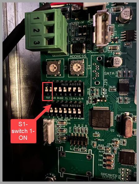
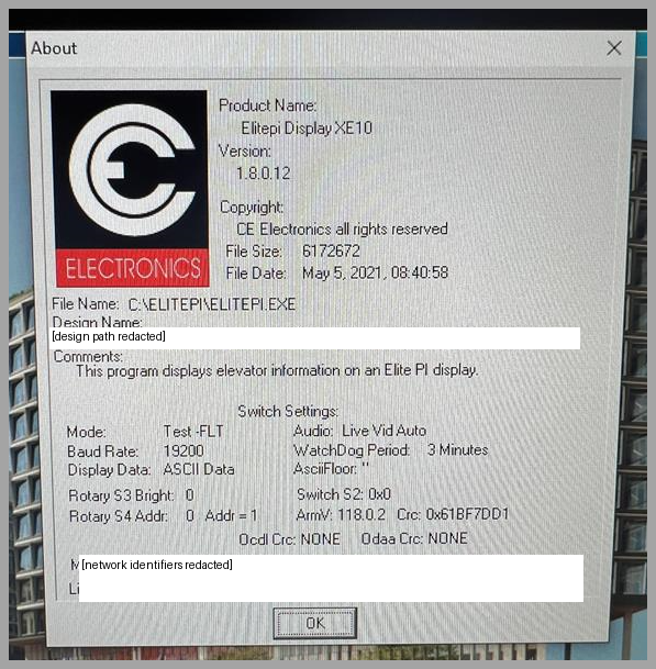
Turn on switch 1, labeled TST, in switch bank S1 on the back of the Elite PI PRO. The diagnostic information screen then appears on the front.
- Locate the two switch banks, S1 and S2, on the back of the unit.
- Set S1 switch 1 (TST) to ON.
- Check the diagnostic information screen on the front. If CE support requests a photo, make sure all the information is visible and the photo is clear.
Still have a question? Ask Elevate AI